The sampling of the motor phase current is indispensable for FOC control. When designing the motor control circuit, in order to accurately sample the current value in the motor winding, it is necessary to improve the anti-interference ability of the current acquisition. So how to ensure that our design is reasonable, Xiaobian takes everyone to discuss the three basic elements of the motor current acquisition circuit.
I. Introduction
Due to the wide range of speed regulation and high speed characteristics of the motor, and the fact that the motor itself cannot obtain the ideal sinusoidal air gap magnetic field, the phase current sampled during system control contains irregular high harmonics and random interference, plus current sampling. The instability of the circuit and the presence of the A/D conversion unit deviation increase the actual sampled current error.
It is well known that the sampling of current is very important for motor vector control. There are three main types of current sampling.
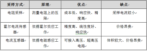
Table 1.1 Current sampling method
For most motor applications, the method of using dual-resistor phase current sampling has certain advantages, so here is a discussion here to discuss how to improve the anti-interference ability of phase current sampling under the double resistance mode.
Second, anti-interference design
1, sampling resistor
Sampling resistors are basic resistor components, and the choice of their parameters is also an important factor in sampling accuracy.
The motor controller samples the two-phase current of the motor through the sampling resistor. As shown in FIG. 1, the voltage signal obtained from the sampling resistor is voltage-biased and amplified, and input to the A/D unit of the microprocessor, thereby obtaining The two-phase current, according to Kirchhoff's law, the sum of the three-phase current vectors is 0, and the value of the current of the third phase is derived.
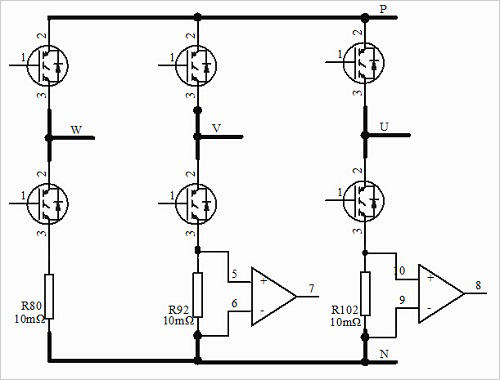
Figure 1 Dual resistance sampling
For a 320V power supply air conditioner compressor, the internal resistance of the motor is 0.2Ω. If the sampling resistor is suitable, it has no effect on the circuit. If the resistance of the sampling resistor is too large, it will cause voltage loss, which will make the energy efficiency lower. A larger resistance value will shift the load voltage and generate electromagnetic interference, which will cause the system to be sensitive to noise. When determining the resistance, it is also necessary to consider the stability and resistance error of the resistor.
2, op amp design
In the circuit design process of the motor, the design of the op amp circuit should be considered. The following is the design description of the phase current sampling circuit. This article uses ON's NCV20034 automotive-grade op amp chip, which has a gain bandwidth of up to 7MHz and integrates four independent op amps.
The op amp chip itself is resistant to common mode interference, while the resistance to differential mode interference is slightly weaker. Therefore, the design should focus on improving the differential mode anti-interference ability on the differential line. As shown in Figure 2, the C2 capacitor is designed to improve the immunity to differential mode interference. The resistors on the differential line (R34, R35) and the feedback resistor (R39) should use high-precision resistors, making the theoretically calculated parameters accurate and reliable. Then, an RC circuit is connected to the AD port pin connected to the output of the operational amplifier to filter out high-order harmonic interference and random pulse interference, thereby improving the anti-interference ability.
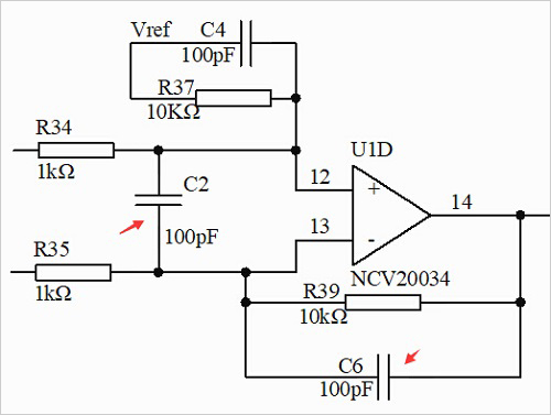
Figure 2 current measurement
3, PCB layout
In order to accurately sample the current, the position of the op amp chip on the PCB should be as close as possible to the sampling resistor, and at the same time, the op amp chip should not be far away from the MCU. The ground of the op amp and the ground of the MCU should be as close as possible. As shown in Figure 3, the sampling resistors (R98, R99, R100) are routed at both ends to the in-phase and inverting ports of the op amp. The differential lines should be equidistant and as short as possible to avoid other interference. The compressor involves high voltage and low voltage parts. When laying the current ground, it should be able to isolate a large current and a small current at a good point.
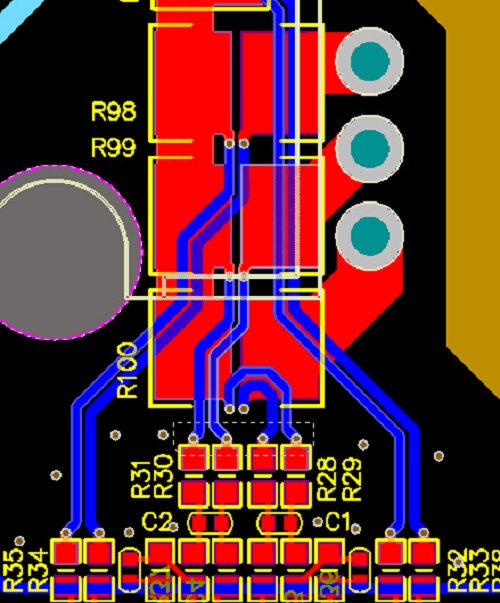
Figure 3 op amp differential trace
After the above hardware filtering, as shown in Figure 4, the 3-phase current waveform is significantly optimized.
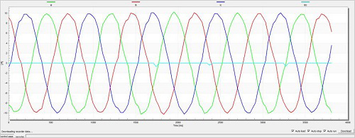
Figure 4 three-phase current waveform
Asbestos was added as an common ingredient to Brake Pads post-WWI, as car speeds began to increase, because research showed that its properties allowed it to absorb the heat (which can reach 500 °F) while still providing the friction necessary to stop a vehicle. However, as the serious health-related hazards of asbestos eventually started to become apparent, other materials had to be found. Asbestos brake pads have largely been replaced by non-asbestos organic (NAO) materials in first world countries. Today, brake pad materials are classified into one of four principal categories, as follows:
Non-metallic materials - these are made from a combination of various synthetic substances bonded into a composite, principally in the form of cellulose, aramid, PAN, and sintered glass. They are gentle on rotors, but produce a fair amount of dust, thus having a short service life.
Semi-metallic materials - synthetics mixed with varying proportions of flaked metals. These are harder than non-metallic pads, more fade-resistant and longer lasting, but at the cost of increased wear to the rotor/drum which then must be replaced sooner. They also require more actuating force than non-metallic pads in order to generate braking torque.
Fully metallic materials - these pads are used only in racing vehicles, and are composed of sintered steel without any synthetic additives. They are very long-lasting, but require more force to slow a vehicle while wearing off the rotors faster. They also tend to be very loud.
Ceramic materials - Composed of clay and porcelain bonded to copper flakes and filaments, these are a good compromise between the durability of the metal pads, grip and fade resistance of the synthetic variety. Their principal drawback, however, is that unlike the previous three types, despite the presence of the copper (which has a high thermal conductivity), ceramic pads generally do not dissipate heat well, which can eventually cause the pads or other components of the braking system to warp.However, because the ceramic materials causes the braking sound to be elevated beyond that of human hearing, they are exceptionally quiet.