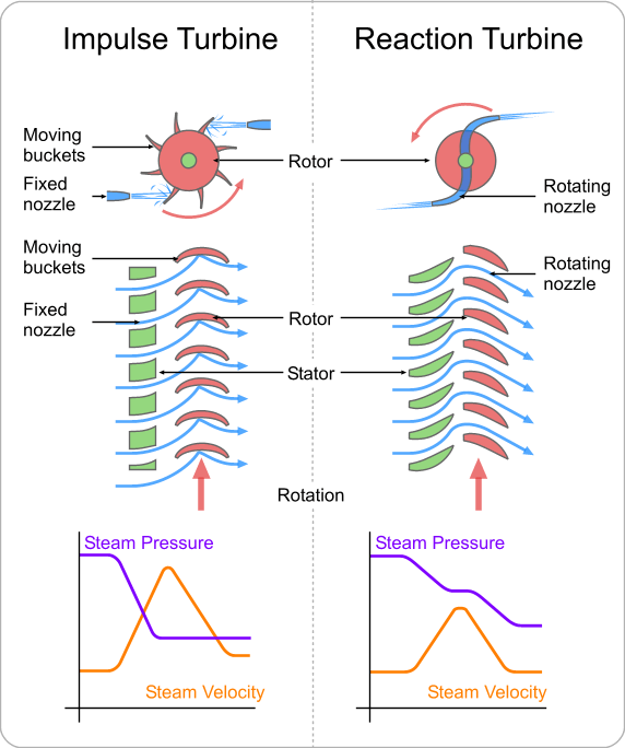
A reaction turbine is a type of Steam Turbine that works on the principle that the rotor spins, as the name suggests, from a reaction force rather than an impact or impulse force.
In a reaction turbine there are no nozzles to direct the steam like in the impulse turbine.
The fixed blades, which are the same shape as the moving blades, are mounted to the outer casing where the rotor revolves and are set to guide the steam into the moving blades. Below is a simple diagram of reaction turbine blades:
In the case of reaction turbine, the moving blades of a turbine are shaped in such a way that the steam expands and drops in pressure as it passes through them. As a result of pressure decrease in the moving blade, a reaction force will be produced. This force will make the blades to rotate.
A reaction turbine has rows of fixed blades alternating with rows of moving blades. The steam expands first in the stationary or fixed blades where it gains some velocity as it drops in pressure. Then enters the moving blades where its direction of flow is changed thus producing an impulse force on the moving blades. In addition, however, the steam upon passing through the moving blades, again expands and further drops in pressure giving a reaction force to the blades.
This sequence is repeated as the steam passes through additional rows of fixed and moving blades.
Note that the steam pressure drops across both the fixed and the moving blades while the absolute velocity rises in the fixed blades and drops in the moving blades.
The distinguishing feature of the reaction turbine is the fact that the pressure does drop across the moving blades. In other words, there is a pressure difference between the inlet to the moving blades and the outlet from the moving blades.
Reaction Steam Turbine Shandong Qingneng Power Co., Ltd. , https://www.steamturbine.be
Application of technology lathe grinding technology in deep hole processing Liaoning Xiuyan County Vocational Education Center (114300) has been opened to facilitate the majority of authors to timely check the processing of submissions, our company has opened "online manuscript inquiry service". For more information and enquiries on submission processing, please log in: Lathe grinding technology is to use a high-speed rotating elastic boring head to grind deep holes mounted on the middle slide on a horizontal lathe.
This technology is one of the most practical deep hole finishing technologies that the author has accumulated and researched in the long-term machine tool processing and teaching practice. It has the following characteristics: 1 high production efficiency, 10 times higher than turning boring. 2The surface roughness is low, the lowest Ra0.8rtm3 can process the workpiece with thin hole wall (the deep hole can be processed with a wall thickness of 2mm). 4 The grinding head is simpler and cheaper, and is suitable for single or small batch production. So how to master and use this technology, we should start from three aspects.
1. Chuck 2 shaft 3. Flange 4 grinding block 5 spring elastic grinding head is composed of four parts: shaft, flange, grinding block and spring. The left end of the shaft is stuck on the chuck, and the right end is threadedly coupled with the flange. The length L is determined according to the hole depth (slightly longer than the hole depth). The right end of the flange is machined with a square hole in the radial direction for mounting the grinding machine. The block and the spring, the grinding block can slide freely in the radial direction in the square hole, and the spring is between the two grinding blocks, and respectively apply elastic force to the two grinding blocks. When grinding, the grinding block is pressed into the square hole, and the two grinding blocks respectively swell against the wall of the hole under the action of the elastic force. When the elastic grinding head rotates at a high speed, the grinding block is evenly ground in the hole.
The choice of the material of the grinding block is generally determined according to the material of the sleeve. The carbon structural steel is generally made of 36 46 white corundum grinding wheel when rough, and the fine grinding is made of 80 or more oil stone.
2. The correct installation of the deep hole sleeve, such as the installation of the tire. The tire is divided into upper and lower parts, and the upper and lower tires 4, 6 are connected by pressing bolts 5 (4). The lower tire 6 is connected with the middle slide (4 compression bolts). The sleeve is cut into the interference fit of the outer diameter of the sleeve before the clamping. The general interference is 0.05. between. Then, take the upper tire 4 down, and then the sleeve to be processed 1. The middle slide plate 2 deep hole sleeve 3. 5. Press the bolt 4 on the tire 6. The lower tire shaft is clamped with a chuck and found Positive, then firmly connected to the flange.
The size of the grinding block should be matched with the square hole size in the flange. The matching clearance is generally 0.1~0.2mm. It can be freely slid by hand.
To ensure adequate cooling during the honing process, 95% of the emulsion is continuously poured.
Surface roughness is controlled by adjusting the grinding block (material and particle size). The dimensional accuracy is mainly based on the shaft speed and the feed speed. In addition, the size range of 70~300mm is the most ideal size section for grinding.
The lathe grinding technology is relatively simple to operate and easy to master, and provides a better process for deep hole processing.
Reaction Turbine Principle:

Reaction Turbine Working:
Special Aspects of Reaction Turbines